
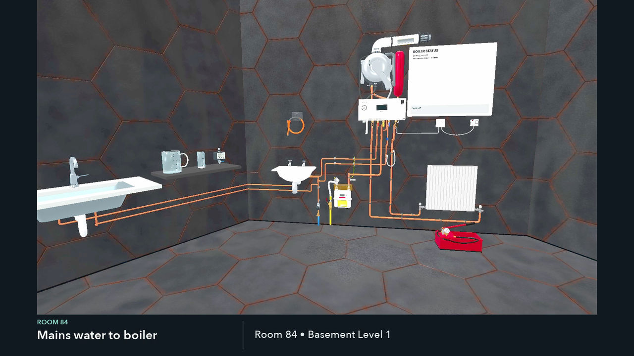
Where is a mains water stop valve usually fitted?
The internal stop valve is normally on the incoming water pipe, before that supply branches off around the property. Its position depends on the original pipe route and later alterations; the room you now call the kitchen may not be where the original kitchen was. Some are near the front door, in an airing cupboard or beneath an accessible floor panel. Identify the incoming cold supply: a valve near a cylinder may control a different part of the system.
- Under the kitchen sink: look towards the back or side of the cupboard and near the floor. Move stored items carefully; do not pull on pipes.
- Utility room or downstairs toilet: check where the cold-water supply enters, including an accessible service cupboard.
- Under-stairs cupboard, garage or cellar: particularly where the incoming pipe enters below or beside the main living space.
- Flats and converted buildings: an individual stop valve may be in the flat, a riser cupboard or a shared service area. Confirm that it controls your supply before operating it.
A small valve on the pipe to a washing machine, tap or toilet usually isolates only that appliance or fitting. It is not necessarily the main stop valve. A traditional internal stop tap often has a T-shaped or wheel handle, but appearance alone does not prove what it controls.
The external stop tap is separate. It may be beneath a small cover near the boundary or meter, and some properties share a supply. Responsibility and permission to operate it depend on the arrangement and water company. Do not assume a valve outside your door serves only your home.
Once identified, keep the route clear, label the valve and show other household members where it is. An access hatch should allow operation and maintenance, not merely a glimpse of the handle.
Which part does what?
Several quite different seals sit close together. Tightening the wrong nut can leave the leak unchanged or create another one. The illustration separates the parts of one conventional washer-type stop valve; it is an explanation of the mechanism, not an exploded parts list for every make.
| Part | What it does | Where it seals |
|---|---|---|
| Handle and spindle | Turn the mechanism to move the closing washer towards or away from its seat. | The spindle passes through a gland or another maker-specific spindle seal. |
| Gland nut and packing | The gland nut compresses packing around the moving spindle on an adjustable packed-gland valve. | Stops water escaping around the spindle beneath the handle. |
| Headwork or bonnet | Carries the spindle assembly and screws into the fixed body. | The headwork-to-body joint uses the seal specified for that design, which may be a fibre washer or another sealing arrangement. |
| Jumper and closing washer | The jumper carries the rubber-like washer that closes against the internal seat. | Stops flow through the valve when closed. Its washer is inside the body, at the end of the mechanism. |
| Copper compression connection | A nut compresses an olive around the copper tube and into the fitting. | The olive forms the seal. It is not a loose flat washer placed across the pipe bore. |
| MDPE connection | A compatible adaptor or reducing stop tap connects the plastic service pipe. | The maker’s specified seal, gripping components and pipe support must match that fitting and pipe. |
The large headwork hexagon and the smaller gland nut are different parts. The large hexagon is not a stronger version of the gland adjustment: undoing it opens the pressurised body of the valve.
Blue MDPE in, 15 mm copper out
A blue plastic service pipe entering from below and a copper pipe continuing upwards is a useful example of an indoor installation. Blue water-service pipe is commonly MDPE, short for medium-density polyethylene. “Alkathene” is often used informally for plastic water pipe, but older polyethylene services come in different sizes and materials. Colour or a familiar name is not enough to select a connector.
The copper outlet in this lesson is 15 mm outside diameter. That does not mean the incoming plastic pipe is 15 mm, or that every house should use a 15 mm outlet. Read the markings and establish the actual pipe type, outside diameter and specification before choosing a valve and transition fitting. The household’s required flow and the existing pipework also matter.
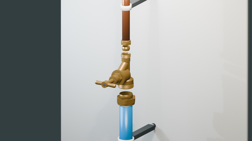
Use a stop tap or adaptor specifically suitable for the incoming plastic pipe and the copper outlet. Fit the correct liner or support insert inside the MDPE where the selected manufacturer requires it. The insert supports the pipe wall at the connection; it is not a closing washer and does not belong inside the valve’s shut-off seat.
For an ordinary copper compression joint, the nut and olive sit around the copper tube outside the waterway. For the plastic side, follow the selected fitting’s own assembly order and insertion requirements. Some systems use a separate grip ring and elastomer seal; others work differently. Do not borrow the order shown for one fitting and apply it to another.
Support and align both pipes so their weight and movement do not load the valve. Follow any flow-direction arrow on the body and the manufacturer’s permitted mounting orientation. The inlet-below arrangement shown here is an example, not a rule that every stop valve must be vertical.
How far should the stop valve be from the wall?
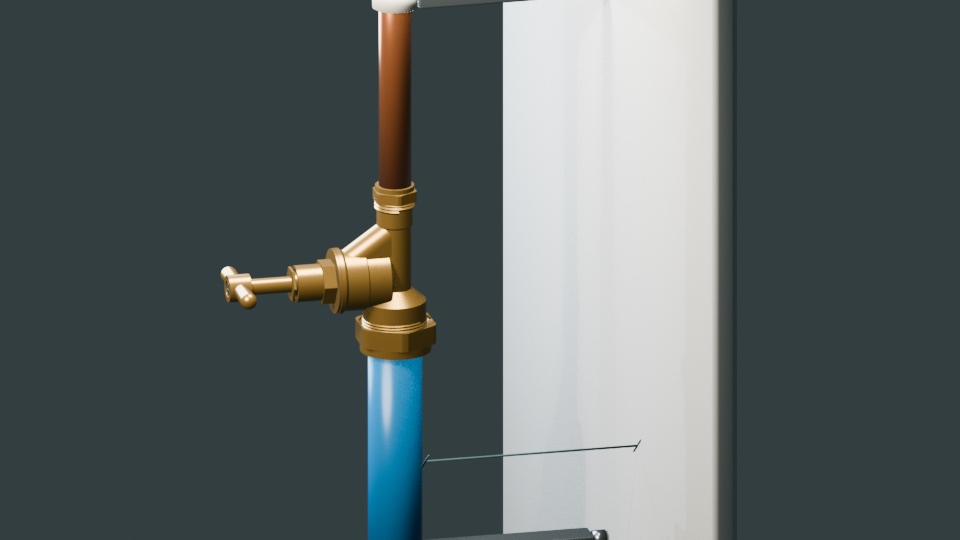
Choose the clearance for the actual valve, tools and service access. There is no single wall distance in this guide that makes every stop valve suitable. A dimension measured to the pipe centreline is also different from the free gap behind the widest part of the valve.
The standalone detail illustration below uses 100 mm from the finished wall to the pipe centreline. This is a dimension of that teaching model, not a recommended minimum or a measurement of the Room 84 installation.
Before fixing the pipe clips, check that there is room to:
- Turn the handle through its full movement without hitting the wall, cupboard or other pipes.
- Seat a correctly fitting spanner squarely on the gland nut and move it through a small adjustment without hitting the wall.
- Reach the inlet and outlet connections without levering the pipes sideways.
- Withdraw the complete headwork and closing washer along the spindle axis after safe isolation.
- Inspect every joint, catch residual water and replace the valve when required.
The largest fitting, the chosen tool and the withdrawal distance may determine the space more than the pipe diameter does. A plumber should confirm the manufacturer’s requirements and the working space on site. Do not bury the gland behind a wall finish or permanently box in the valve.
Where a pipe passes through the building fabric, the entry also needs appropriate protection and sealing. Protect pipework from freezing where required, while preserving access to the valve and its joints.
How to turn off the incoming water
For a conventional multi-turn stop tap, turn the handle clockwise gently to close. Do not use grips or a long lever to force the handle. Quarter-turn valves operate differently, so first identify the type you have.
Check the result at a cold tap known to be fed directly from the mains: the flow should reduce and stop as the downstream pressure is relieved. A valve that turns does not necessarily seal. If water continues to flow, the wrong valve may have been operated, the supply may have another route, or the closing washer or seat may be faulty.
Turning off the incoming supply does not empty storage tanks, cylinders or every pipe. Gravity-fed outlets can continue to run, and isolated sections can retain pressure. Do not treat a stopped kitchen tap as proof that an unrelated hot-water or heating system is safe to dismantle.
If the handle is seized, the spindle is damaged or the body starts to move with the handle, stop. Arrange a plumber and confirm an upstream isolation route. In a serious leak, contact the water company if external isolation is needed and you cannot safely identify or operate the correct valve.
Find the leak before reaching for a tool
Dry the valve and nearby pipework, then watch where fresh water first appears. Water can travel down a pipe or around a nut, so a drip at the lowest point may have started higher up. Condensation on a cold pipe can also resemble a leaking joint.
| Where water appears | What needs checking |
|---|---|
| Around the spindle, below the handle | The gland packing or spindle seal. A small adjustment may help only if this is an adjustable packed-gland design. |
| At the large headwork-to-body joint | The bonnet seal, joint or damaged parts. This is not corrected by tightening the small gland nut. |
| At an inlet or outlet pipe nut | The relevant compression connection, pipe condition, alignment and correct components. |
| Through the body itself | A crack, corrosion or another body defect. Further tightening is not a repair for a damaged casting. |
| No external drip, but the valve will not stop flow | The closing washer and seat, correct valve identification and any alternative supply path. |
If there is substantial leakage, corrosion, a distorted pipe or uncertainty over which joint is wet, isolate safely and obtain help. Keep water away from electrical equipment; do not reach through water to touch a switch or appliance.
What tightening a leaking gland actually does
On a traditional adjustable packed gland, a modest tightening of the gland nut compresses the packing more firmly around the spindle. This can stop a minor seep from that seal. It does not repair a scored spindle, failed packing or a leak elsewhere, and too much compression can make the handle difficult to turn.
The standalone illustration below shows one correctly fitting spanner on the small gland nut. An adjustment of ⅛ of a turn (45°) is a useful small-movement example. Sometimes that is enough to stop a minor seep, but the amount needed depends on the actual valve and packing. It is not a fixed required turn, a guaranteed repair or a measured turn in Room 84.
The larger bonnet stays fully fitted throughout this adjustment. Keep the valve and connected pipes from twisting, and stop if the bonnet, fixed body or either pipe moves.
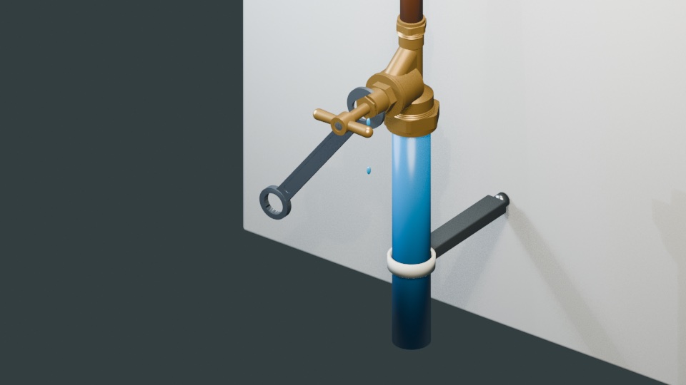
- Identify the design and leak. Confirm that the wet point is the adjustable gland, rather than the bonnet or pipe connection. Establish a reliable upstream isolation method before starting.
- Use a spanner that fits. Seat it squarely on the gland nut’s flats. Do not use the spindle or pipe as a tool contact point.
- Prevent twisting. Keep the complete valve and its pipework stationary. If they move with the spanner, stop and reassess the support and repair method.
- Adjust only as much as needed. Follow the valve maker’s maintenance instructions and check after a small movement. Do not continue tightening merely to reach an example angle.
- Check both sealing and movement. The seep should cease and the handle must remain reasonably free. If the leak continues or the handle becomes stiff, stop tightening and arrange proper repair or replacement.
Do not loosen or remove the gland to try this adjustment. Removing a gland nut or adding packing opens a different maintenance task and requires appropriate isolation and depressurisation. A demonstration of a minor external adjustment is not permission to dismantle a live mains valve.
Undoing the headwork: why upstream isolation matters
Closing this stop valve does not make its body safe to open. The incoming side can still be under mains pressure. Before the large headwork or any pressure-retaining connection is loosened, isolate upstream, relieve pressure and establish that isolation is effective.
In the exploded detail illustration, the large removable assembly is the headwork or bonnet. The fixed body remains connected to the inlet and outlet pipes. Separating these parts lets you see the spindle, gland, closing washer and seat; it should not be copied on a live supply.
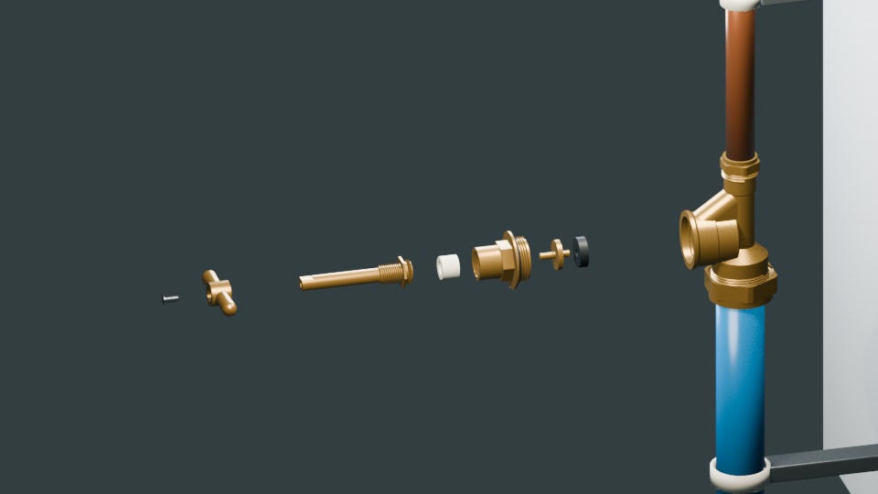
A plumber first confirms the correct upstream valve and any shared-supply implications. After isolation, the connected system is depressurised and the absence of flow is checked. Residual water still needs to be contained. If upstream isolation cannot be proved, the headwork stays fitted.
During service, the body is supported while the headwork is removed. The closing washer must be the correct size and type for the mechanism and suitable for drinking-water use. The headwork seal and any retaining component must also match the valve. A worn seat, damaged thread, seized mechanism or badly corroded body can make replacing the complete valve the better repair.
Reassembly follows the manufacturer’s instructions, including which seals must be renewed. Do not stack spare washers into a joint or apply sealing tape indiscriminately. Different connections seal in different places; a compression nut’s threads, for example, are not the sealing face of its olive joint.
After reassembly, restore the supply gradually, check for leakage and confirm that the valve both opens and closes properly. Inspect again after operating it. The person doing the work must be able to isolate the supply again promptly if a joint leaks.
Follow the water through the valve and up to the tap
The standalone cutaway below reveals the waterway inside the valve. With the closing washer lifted clear of its seat, water can pass through the valve and continue along the connected pipework to an open outlet.
Seating the closing washer stops flow through the stop valve. This is a different seal from the gland packing around the spindle: the gland prevents an external seep while the spindle moves.
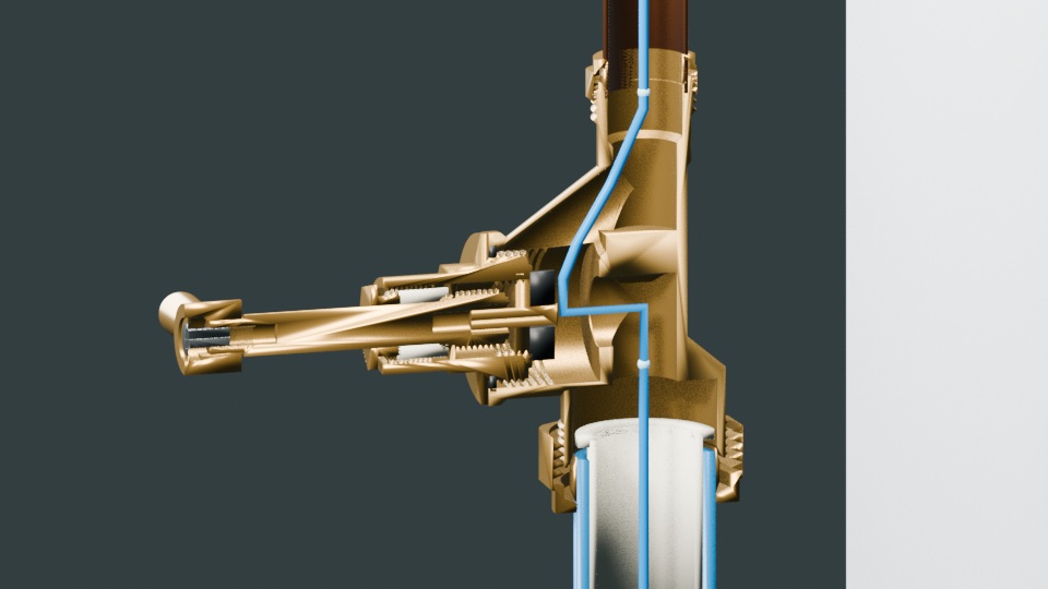
The removed half exposes the seat and internal passage; the cut faces do not represent leaks or holes in a working valve. Room 84 also opens the valve for a closer look during its stop-valve chapter.
Water pressure, flow and older houses
Pressure is the force available to move the water; flow is the volume delivered over time. Pressure is commonly measured in bar, and flow in litres per minute. A tap can have apparently reasonable pressure when closed but deliver too little water when opened, especially through a restricted pipe or valve.
Static pressure is measured with no water being drawn from the part of the supply being tested. Dynamic, or running, pressure is measured while water is flowing. Record where and how the reading was taken: a no-flow reading near the incoming supply and a running reading at an upstairs shower are not interchangeable measurements.
For England and Wales, Ofwat describes the Guaranteed Standards Scheme minimum as seven metres of static head in the communication pipe—approximately 0.7 bar. This is a supply standard with defined conditions and exceptions, not a design target or a promise of 0.7 bar at every tap. Static head is a pressure measure, so it must not be presented as a guaranteed outlet flow rate.
There is no single figure in this guide that establishes acceptable performance for every UK house. Check your own supplier’s service commitments and the pressure and flow required by your actual appliances. A boundary measurement does not include all the effects of private pipework, height and simultaneous use inside the home.
WaterSafe says most suppliers aim for around 10 metres head, approximately 1 bar, at the end of the communication pipe. Scottish Water separately states an aim of 1 bar at the point where its pipework connects to the property’s pipework. For a property in Northern Ireland, check the applicable commitment with NI Water. Do not apply the England and Wales figure across the whole UK.
A mains-fed reading below about 1 bar is worth investigating alongside flow and appliance requirements, especially if performance has deteriorated. It is not, by itself, proof of a supplier breach or a diagnosis of a faulty stop valve. Record whether it is a static or running reading and where it was taken.
An older house does not automatically have low pressure. A small or long service pipe, a shared supply, partly closed stop valves, internal corrosion, a blocked filter or several outlets running together can reduce flow. Some older properties have lead or steel pipework, but identify the actual material rather than guessing from the house’s age. Suspected lead pipe needs the water company’s advice on identification and replacement, not just a pressure remedy.
Height matters too. In a stationary water column, each metre of rise uses roughly 0.1 bar of pressure. When water is flowing, pipes, fittings and valves cause additional losses. This is why a reading near the incoming stop valve does not by itself establish the pressure available at the top-floor shower.
A loft storage tank is a different arrangement from a direct mains supply: the height of the water above the outlet provides the gravity head. A poor shower fed from a tank may need a different investigation from a poor mains-fed kitchen tap. Establish which system supplies the affected outlet before considering a pump or other alteration.
What pressure is recommended for a home?
About 1.5–3 bar at the draw-off point, such as a tap, is a useful domestic design guide. That is the recommended operating range in Caleffi’s domestic pressure-control guide. It is not a measured UK household average, a supplier’s guaranteed minimum or the right setting for every installation. Check the working requirements of the actual taps, shower, boiler and other appliances.
Caleffi’s EN 806-3 summary separately gives 1 bar minimum dynamic pressure and 5 bar maximum static pressure at draw-off points. Keep those test conditions distinct. These are attributed design references, not a universal legal cut-off. Persistent readings above 5 bar merit a plumber’s assessment; a particular fitting or installation may need a lower limit.
A good static reading does not establish adequate delivery when several outlets run. Conversely, noise or a dripping tap alone does not establish excessive pressure. Measure it, compare the results with the equipment requirements, and investigate the cause. A pressure-reducing valve can control excessive incoming pressure when correctly selected; it cannot cure every restriction or pressure surge.
What pressure does a combi boiler need?
A combi needs sufficient cold mains pressure while water is flowing, together with enough incoming flow to deliver its hot-water output. Its minimum operating threshold and the supply needed for maximum performance are different. A kitchen-tap test is useful evidence, but pipe losses and simultaneous demand mean it does not prove the conditions at the boiler inlet.
System and heat-only boilers with stored hot water, and open-vented heating systems, do not all share the combi inlet or sealed-system gauge requirements described here.
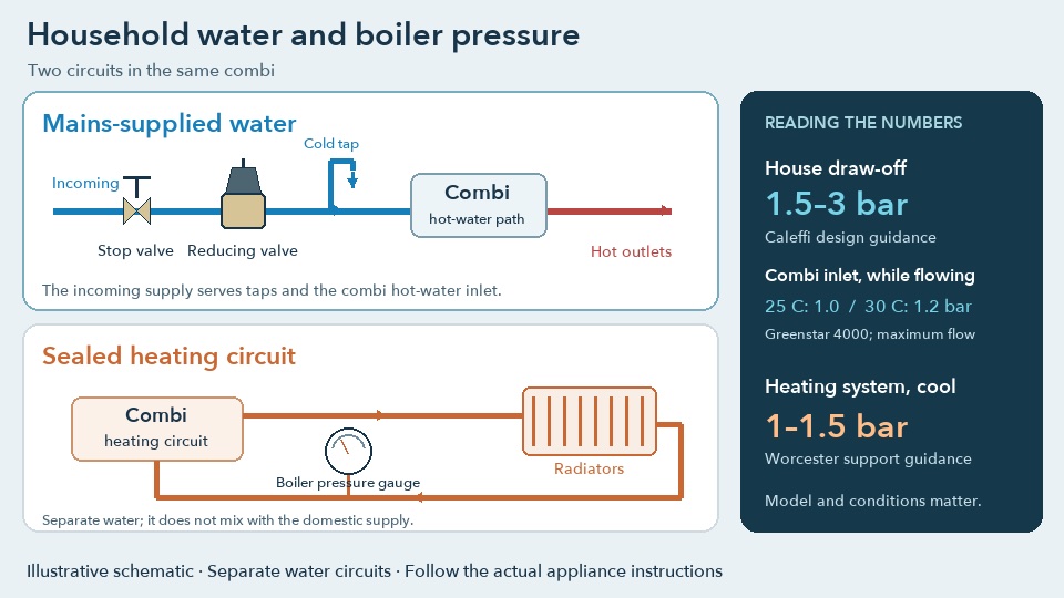
| Water-supply requirement | 25 C | 30 C |
|---|---|---|
| Minimum working mains pressure for maximum flow | 1.0 bar | 1.2 bar |
| Minimum working mains pressure for operation | 0.2 bar | 0.2 bar |
| Flow needed to activate hot-water demand | 1.9 litres/minute | 1.9 litres/minute |
| Maximum hot-water flow at a 40°C temperature rise, ±15% | 9 litres/minute | 11 litres/minute |
The manual specifies a flow regulator for the 40°C rise. Its lower pressure and activation figures are not shower-comfort targets or proof of full hot-water output. The appliance instructions and system design determine the required supply; another model may differ.
The boiler’s heating gauge measures a separate circuit
The pressure shown on a sealed central-heating system is separate from the cold mains feeding the taps and combi hot-water side. Worcester Bosch’s household guidance gives 1–1.5 bar when the heating system is cool; follow the actual appliance instructions. Do not adjust the house’s pressure-reducing valve to make the boiler heating gauge reach that number.
A large pressure rise as the heating warms, or repeated loss of pressure, needs investigation. Worcester advises an engineer’s check where the rise exceeds 1 bar. This is a heating-system issue, rather than evidence that the incoming mains pressure is too low.
How can you check water pressure and flow?
Go to the tap-testing chapter in Room 84
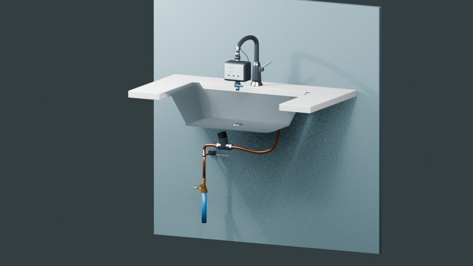
Room 84 compares a running pressure reading with a static reading, then uses two timed jug tests to investigate a weak hot tap. The readings belong to the training installation; they are not measurements from your home.
A timed container test measures flow
At a suitable cold tap known to be mains-fed, fill a container of known volume and time it. Keep the test controlled to avoid splashing or overflowing. Calculate litres per minute = litres collected × 60 ÷ seconds taken. For example, 4.5 litres in 30 seconds would be 9 litres per minute.
Room 84 uses the same calculation for two hot-tap tests: 0.87 litres in 30 seconds is about 1.7 litres per minute, while 3.49 litres in 30 seconds is about 7 litres per minute. In that exercise, opening the restricted stop valve improves the delivered flow while the sealed heating gauge stays at 1.5 bar. These are training examples, not a diagnosis for every weak hot tap.
Record which tap you used, whether other outlets were running and the time of day. An aerator, tap design or local valve can limit the result. This test measures delivery from that outlet; it does not measure pressure or prove what the supplier delivers at the property boundary.
An engineer’s flow cup is a different measuring tool
A calibrated flow cup can indicate steady outlet flow in litres per minute while water drains through it. Use that instrument’s own scale and instructions, and keep its drain unobstructed. It measures flow, not pressure. The cup in the animation illustrates the principle; its simplified geometry is not a calibration drawing or a specification for making a measuring instrument.
A digital tester connected to the tap measures pressure and flow
The illustration uses an unbranded flow-through tester attached through a compatible aerator adaptor. Water passes through its body to a downstream discharge valve. The principle follows Salamander Pumps’ AquaScan guidance; the simplified model does not claim that product’s calibration or certification.
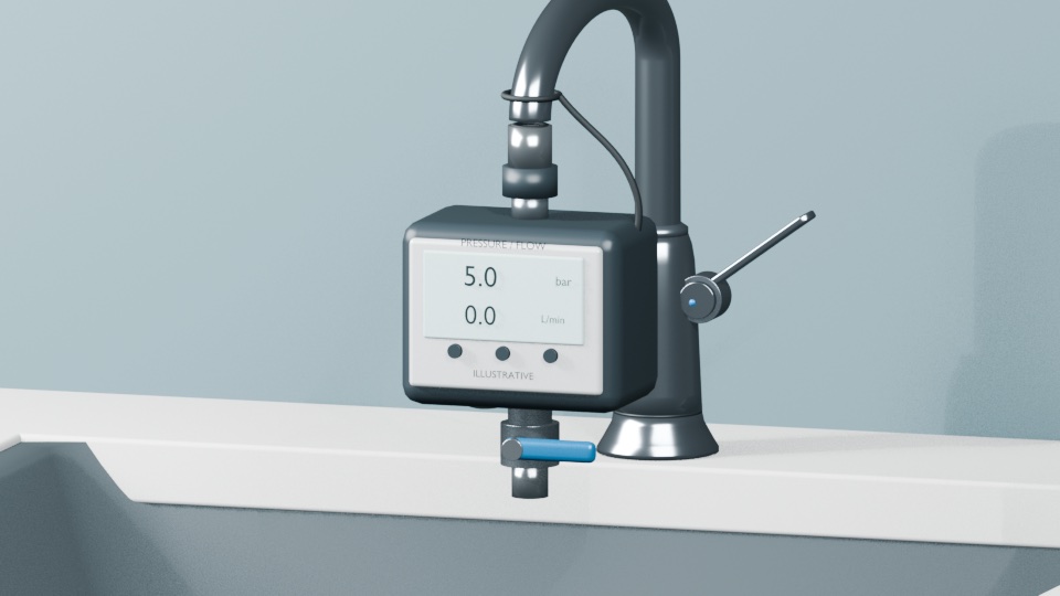
- Connect with the tap off. Remove the aerator only where the tap and matching adaptor permit. Fit the specified seals, follow the tester’s connection instructions and support its weight and hose without straining the spout. Use a drinking-water-suitable tester, connectors and hose with appropriate pressure ratings and measurement range.
- Establish flow. Direct discharge safely into the sink, open the tester’s outlet valve and open the cold tap gradually, then fully. Keep the tap fully open for these static and running comparisons. Avoid a kinked hose.
- Read static pressure. Keep the supplying tap open, close the tester’s downstream valve and close other outlets. Flow stops. Allow 30–60 seconds for the reading to settle.
- Read running pressure and flow. Open the tester’s discharge valve so water flows through it. After another 30–60 seconds, record the live pressure in bar and the accompanying flow in litres per minute.
- Release before removing. Shut the tap, open the discharge path to release trapped pressure, confirm a zero pressure indication, then detach the tester.
Room 84’s tap-testing chapter shows about 2.4 bar while delivering 6.2 litres per minute, followed by 3 bar with no flow when the tester’s discharge closes and no other outlet is running. Its readings are examples, not measurements from your home. A plain closed-end gauge needs flow drawn elsewhere for a running-pressure check; opening a tap into a sealed gauge alone is still a no-flow test.
The adapter, tester and valve can restrict delivery. Do not equate their instrumented flow reading with the separate jug result. Compare readings taken with the same arrangement and valve positions. If the tap cannot accept a secure compatible connection, use a plumber’s suitable test point.
Use the pattern to choose the next step
| Pattern | Useful next check | Who can help |
|---|---|---|
| One outlet affected | Tap aerator, local isolation valve and that branch pipe. | A plumber if a simple accessible blockage is not the explanation. |
| Several mains-fed outlets affected | Supply incident, incoming valve, filters and service pipe. | Water company for network concerns; plumber for the private installation. |
| Good static reading, large drop under demand | Restrictions, long or undersized pipework, shared supply and simultaneous use. | Plumber to compare pressure and flow; supplier if delivery to the property is in question. |
| Only hot water or a tank-fed outlet affected | The actual hot-water or gravity-fed arrangement. | A plumber or appropriately competent heating engineer for that system. |
| High static pressure or recurring surges | Measured pressure against equipment ratings and the cause of transients. | Plumber for suitable pressure control and fault investigation. |
Keep a useful test record: date and time; exact test point and floor; mains-fed or tank-fed; static pressure; running pressure and the flow drawn during that reading; container volume and elapsed time; other outlets in use; and whether the symptom changes during the day. These details are more useful than reporting “the pressure seems low”.
Take repeat readings if the problem is intermittent. A single kitchen-tap result cannot determine whether a supplier’s boundary service standard has been met; ask the water company to investigate supply concerns and use a plumber for faults within the property.
How a pressure-reducing valve lowers excessive pressure
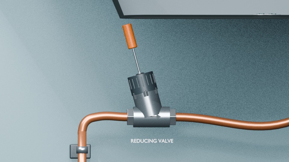
A pressure-reducing valve controls the pressure supplied to downstream pipework. It is different from the main stop valve and from a boiler’s pressure-relief safety valve, even though both devices may be called a “PRV”. Part-closing a stop tap restricts flow but does not reliably limit static pressure.
The reducer belongs downstream of the stop valve, with its flow arrow pointing towards the supplied pipework. The standalone detail illustration below uses a horizontal pipe and upward-facing cover; Room 84 places its reducer above the stop valve. Follow the selected model’s orientation instructions, support both pipes and provide isolation and space for the adjustment, gauge, strainer and servicing.
Lower the setting, draw water, then recheck
For the illustrated screw-adjusted type, turning anticlockwise lowers the setting; clockwise raises it. Check the actual manufacturer’s direction and procedure. There is no universal number of turns per bar. Adjust the setting control only: opening the cover or removing a cartridge is separate maintenance requiring isolation and depressurisation.
Turning the setting down does not vent pressure already trapped downstream. Draw water through a suitable outlet, close it again, let the pressure settle and recheck the static reading. Also check the pressure available while drawing the required flow. Size and select the reducer for the installation, since running pressure can fall below its no-flow setting.
| Stage | Reducer setting | Downstream pressure |
|---|---|---|
| Both taps shut, before adjustment | 5 bar | 5 bar |
| Setting reduced, taps still shut | 3.5 bar | Can remain at 5 bar |
| Open a tap, then close it and recheck | 3.5 bar | Settles at 3.5 bar in this example |
These values explain the different states; they are not a measured product performance curve or a guaranteed result from a fixed turn. The training room’s 3.5 bar setting is not a recommendation for your home. Check the household and appliance requirements, including pressure while drawing the required flow.
A reducer cannot raise an inadequate incoming supply. If downstream pressure creeps up or surges recur, investigate the cause: debris at the valve seat, thermal expansion and water hammer are different problems. Reducing the setting repeatedly is not a substitute for diagnosis and suitable expansion or surge protection.
Keep it usable before an emergency
- Keep the handle, gland and both connections accessible. Avoid storing heavy items against the pipework.
- Look for fresh dampness, green deposits, corrosion and staining. Dry old staining alone does not prove an active leak.
- Check periodically that the valve can be operated gently and actually shuts the supply, following the manufacturer’s or water company’s guidance.
- When reopening a traditional stop tap, do not jam the handle hard against its fully open stop. Follow the guidance for the particular valve.
- Record the location and the correct upstream isolation arrangement. Shared buildings need a clear account of which homes a valve affects.
- Arrange attention before a stiff handle or slow seep becomes an emergency. Do not leave a tool attached as a substitute for a usable handle.
If you need help with a leaking or seized valve, see EPHG’s emergency plumbing service or call 07720 247247.
Common stop-valve questions
Is a stopcock the same as a stop tap or stop valve?
In everyday UK usage, these names often describe the valve that shuts off the incoming water. “Stop valve” is a broader term, so check the actual valve type and the pipe it controls.
Will tightening the gland fix every leak?
No. It may help a minor seep around an adjustable packed spindle gland. A headwork seal, pipe connection, closing washer or cracked body is a separate fault and needs the appropriate repair.
Can I remove the top after closing the handle?
No. The inlet side may still be under mains pressure. Headwork removal requires effective upstream isolation and depressurisation, with the arrangement checked by the person carrying out the work.
Does blue plastic pipe always take the same insert?
No. Match the insert, connector and assembly method to the identified pipe and fitting. Do not assume that an older pipe called “Alkathene” has the same dimensions as modern metric MDPE.
Does the valve have to be a set distance from the wall?
Use the manufacturer’s requirements and sufficient practical access for the handle, tools, both connections and headwork withdrawal. A single general dimension cannot establish that all of these are possible.
Why is there still water after I turn it off?
Some water may be draining from pipes or a storage tank. Continuing mains-fed flow can mean a valve that does not seal, the wrong valve or another supply route. Establish the cause before opening any fitting.
Does the pressure gauge on my boiler show the mains pressure?
Usually it shows the sealed central-heating circuit, which is separate from the incoming mains and combi hot-water supply. Worcester’s guidance of 1–1.5 bar applies when that heating system is cool. See the boiler-pressure explanation; do not use the heating gauge as a mains test or adjust the house reducer to that number.
Can partially closing the stop tap reduce house pressure?
It can restrict flow, but it does not reliably control the static pressure once outlets close. Use a properly selected pressure-reducing valve where pressure control is needed.
Is 5 bar the legal maximum for every house?
This guide does not treat 5 bar as a universal legal limit. It is a useful static-pressure design reference in the cited manufacturer’s guidance. Assess the installation and the ratings of its actual components; lower limits can apply.
Sources and further reading
- Thames Water, How to find and use your inside stop valve; accessed 16 November 2026. Location, shared arrangements and operation.
- Water Regs UK, Why do customers need their own stop valves?; accessed 16 November 2026. Accessible and identifiable customer stop valves.
- Pegler, Valve installation instructions, document 20952253, page 3; accessed 16 November 2026. General gland maintenance, depressurisation before repacking or bonnet work, and support during maintenance. This is general valve guidance, not identification of the model illustrated.
- Aliaxis / Philmac, Philmac Installer Guide, version 4, July 2025, printed pages 4–5, 8–9 and 12; accessed 16 November 2026. Product-specific pipe liners and polyethylene-to-copper connection components.
- Ofwat, Water pressure; accessed 16 November 2026. The England and Wales guaranteed standard and factors affecting supply performance.
- WaterSafe, What is the minimum water pressure that a water supplier must supply?; accessed 16 November 2026. Pressure standards and a simple outlet-flow indication.
- Scottish Water, Your water pressure explained, publication SW YWPE 08/21, printed pages 1 and 4; accessed 16 November 2026. Scottish Water’s pressure aim and the distinction between direct, indirect and heating systems.
- Water Regs UK, How do you find out what the system maximum operating pressure is? and guidance on access to fittings; accessed 16 November 2026. Pressure measurement and access for maintenance.
- Caleffi, Pressure Reducing Valves for Domestic Water Systems, publication 03301 EN, pages 10, 14, 27 and 34–35; reviewed 16–17 November 2026. Manufacturer pressure guidance, permitted orientations and fault distinctions; its EN 806-3 summary is not presented as a universal statutory limit.
- Salamander Pumps, AquaScan User Guide, issue 1.0, August 2024, printed pages 24–25, 28–31 and 43; accessed 17 November 2026. Tap adapters, static and running tests, measurement limits and safe disconnection. The film uses an unbranded explanatory tester.
- Caleffi, 533…H Series Pressure Reducing Valves, technical brochure 01252/17 GB, pages 3–5; accessed 17 November 2026. Regulating principle, pressure loss, setting direction and installation considerations for that family.
- Worcester Bosch, Greenstar 4000 Installation and Maintenance Instructions, document 6 720 891 161, October 2021, Table 33, pages 84–85; downloaded from the manufacturer on 17 November 2026. Model-specific water-pressure, activation-flow and hot-water-output examples; follow the instructions for the actual appliance.
- Worcester Bosch, How often should I need to top up the pressure in the heating system?; accessed 17 November 2026. Cool heating-system pressure and abnormal pressure rise.
Follow the installation and maintenance instructions supplied with the actual valve and pipe connector. Those instructions determine compatible components, seals, assembly and permitted maintenance for that product.